Designing patterned structures requires significant expertise and complex computational systems. We developed a modelling system that provides simple ways to integrate creativity and rigor in the conceptual design of such structures through the combination of geometric rules, optimization techniques, and a novel analysis method. The framework allows to interweave pattern modelling and structural optimization in design-oriented ways. It offers designers creative and systematic ways to explore uncharted territories in high-performance structural design for architecture.
With Caitlin Mueller
Patterns in architecture have long been used for symbolic meaning or ornamental purposes. Often associated with deep vernacular meaning and symbolism, as in Gothic and Islamic architecture, patterns can be both ornamental and functional. Their use in architecture and structural works is uninterrupted throughout the history of construction, and the twenty-first century is no exception. In particular, there has been a recent surge in the performative use of patterns, particularly in structural engineering as contemporary structural engineers and architects cleverly use them to reduce the use of structural materials and to provide aesthetic and experiential qualities to their designs.
Contemporary CAD software employs Non-Uniform Rational B-Splines (NURBS) as their main geometry format for curve and surface modelling. The work presented here is similarly underpinned by the use of NURBS, which makes it generally applicable in most CAD environments. Parametrized surfaces, including NURBS, map a 2D parametric space onto a surface in dimension 3. Any two-dimensional object defined in the pa-rameter space can thus undergo the same mapping, which makes for a convenient way to describe mapped patterns. Specifically, physical trimming curves are defined as mappings of curves which differentiate solid from void in the parameter domain.
Manipulating patterns directly on a non-planar surface is hard, because it entails manipulating 3D curves while enforcing that they lie locally in the tangent plane of the surface. But, doing so in the parameter space automatically ensures it, because the pattern curves undergo the same mapping as any point in the parameter space. Computationally, this is certainly less intensive. From a modelling standpoint, operating on curves indirectly in the parameter space may be frustrating; a solution is to define trimming curves directly in the physical space, through projections or Boolean operations, and subsequently pull them back in the parameter space. Once pulled back in the parameter space, the curves may be modified in the parameter space.
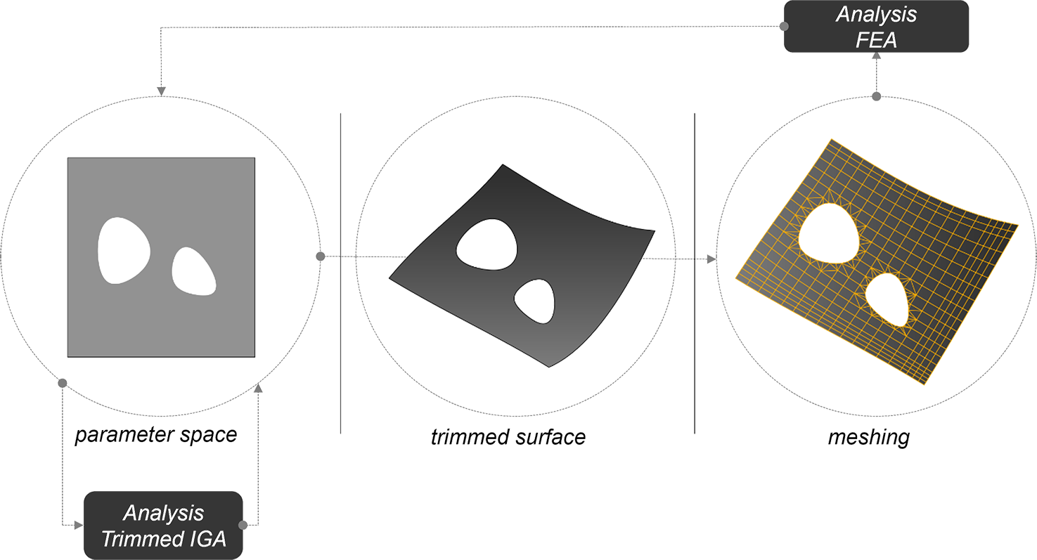
In 2005, Hughes, Cottrell, & Bazilevs introduced the concept of isogeometric analysis. The method shares common features with the finite element method and meshless methods and its main underlying objective is to unify CAD and finite element analysis. Specifically, they propose to match the exact NURBS geome-try of a problem with the analysis model by using the NURBS basis functions to ap-proximate the solution. The method does not require any form of meshing, and it alleviates some of the drawbacks of classical finite element analysis; more important-ly, it allows for streamlined modelling workflows between parameter and physical space, which justifies its use for the present research.
An initial drawback of isogeometric analysis was its inability to deal with trimmed geometries, which stems from the absence of a mathematical relationship between parametrized surfaces and their trimming curves. As a result, in the early days of the method, geometries with complex topologies had to be reconstructed into multiple NURBS patches to become analysis-ready, which defeated the initial intent of the method itself.
Fortunately, multiple approaches have been put forth since then: surface refinement, trimming curve approximation, and surface reconstruction. The authors have developed a novel method for trimmed isogeometric analysis that differs from existing work in that it requires neither refinement, nor simplification, nor surface reconstruction. Similarly to classical finite element analysis, isogeometric analysis requires integration over the domain in order to build the stiffness matrix used in analysis. In isogeometric analy-sis, integration is performed over the parameter space, itself divided in quadrilateral cells. When the parameter space is made up of alternative regions of void and solid, there is a need for an adapted integration scheme. Our method identifies trimmed integration cells, and builds cells with arbitrary NURBS boundaries. Integration is then performed on each arbitrary domain. This method is appropriate for our purposes because, with it, the numerical legwork is performed in the parameter space. Therefore, we can fully describe the patterns in the latter, while the 3D trimming curves never need to be accessed nor manipulated by our algorithms, except for design visualization. Our method is particularly appropriate for optimization procedures. In contrast, with regular finite element methods, a surface needs to be physically trimmed and meshed to become analysis-ready, a computationally intensive process that is less suitable for iterative workflows that require re-trimming and re-meshing at each step.
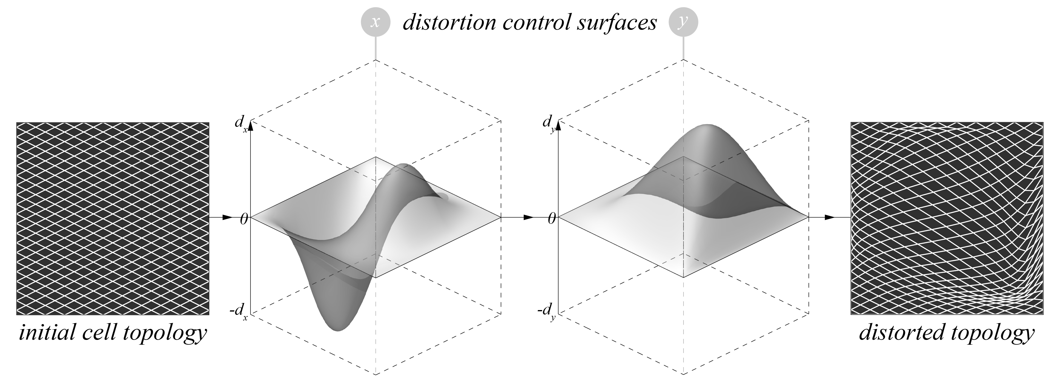
This work relies on a workflow integrating geometric operations on a set of pattern operations applied on a human-designed initial cell topology. The operations include scaling and grid distortion. The operation sequences are diagrammed below.
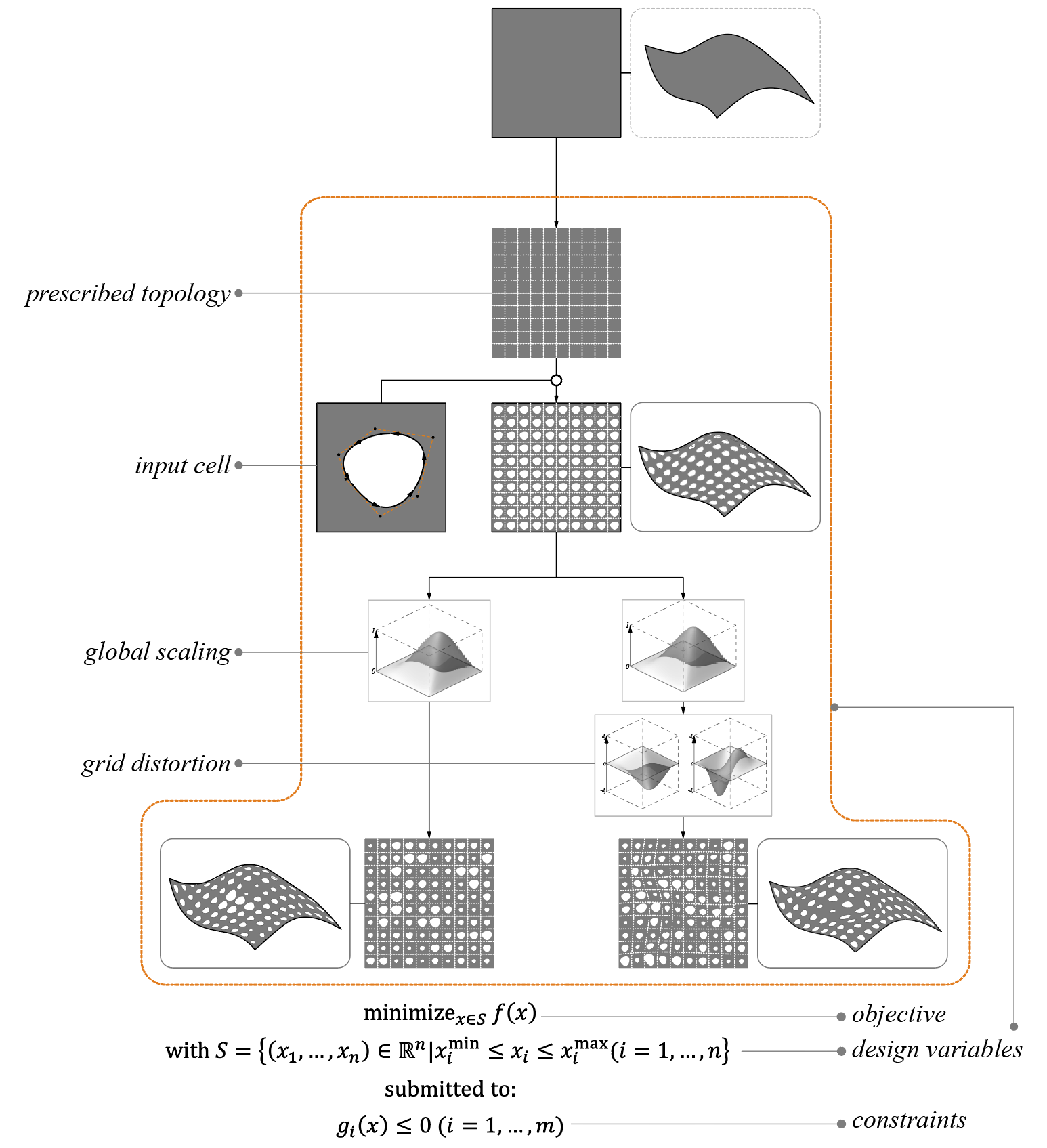
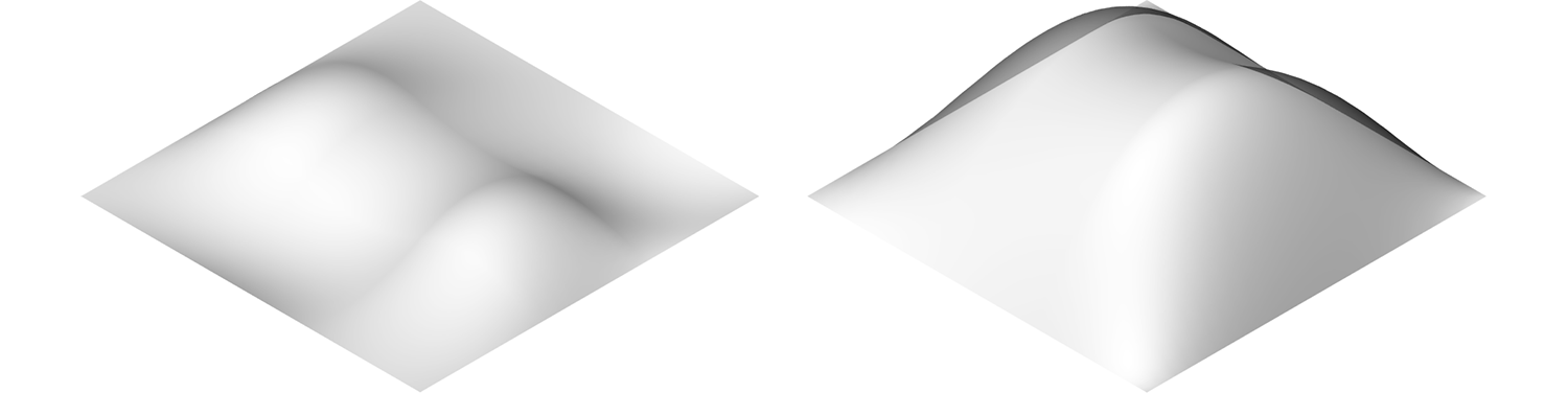
The scheme starts with an input topology and an associated connectivity that remains unchanged. This topology is populated with predefined shapes. These cells are then scaled using a scaling control surface. Compared to an individual scaling of each curve, the use of a scaling control surface has two advantages: first, the designer gains control through the type of surface chosen, smooth or step-like for example, and, second, the control surface greatly decreases the number of design variables for dense patterns.
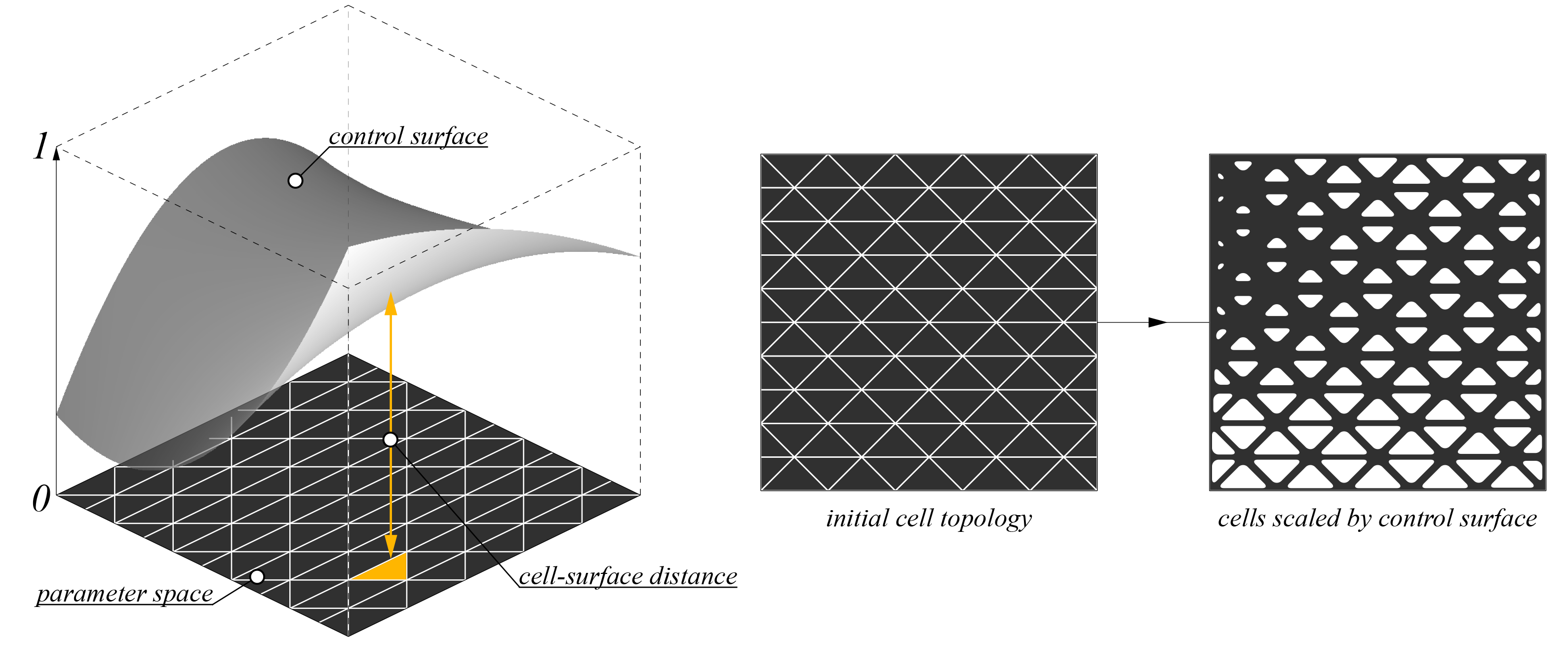
Similarly, the designer has the possibility to incorporate distortion of the initial topology in the process, again using control surfaces. The resulting surface can be optimized by controlling the variables affecting the scaling, and distortion, which are most often described by control points, and the system can accommodate an infinite variety of patterns.
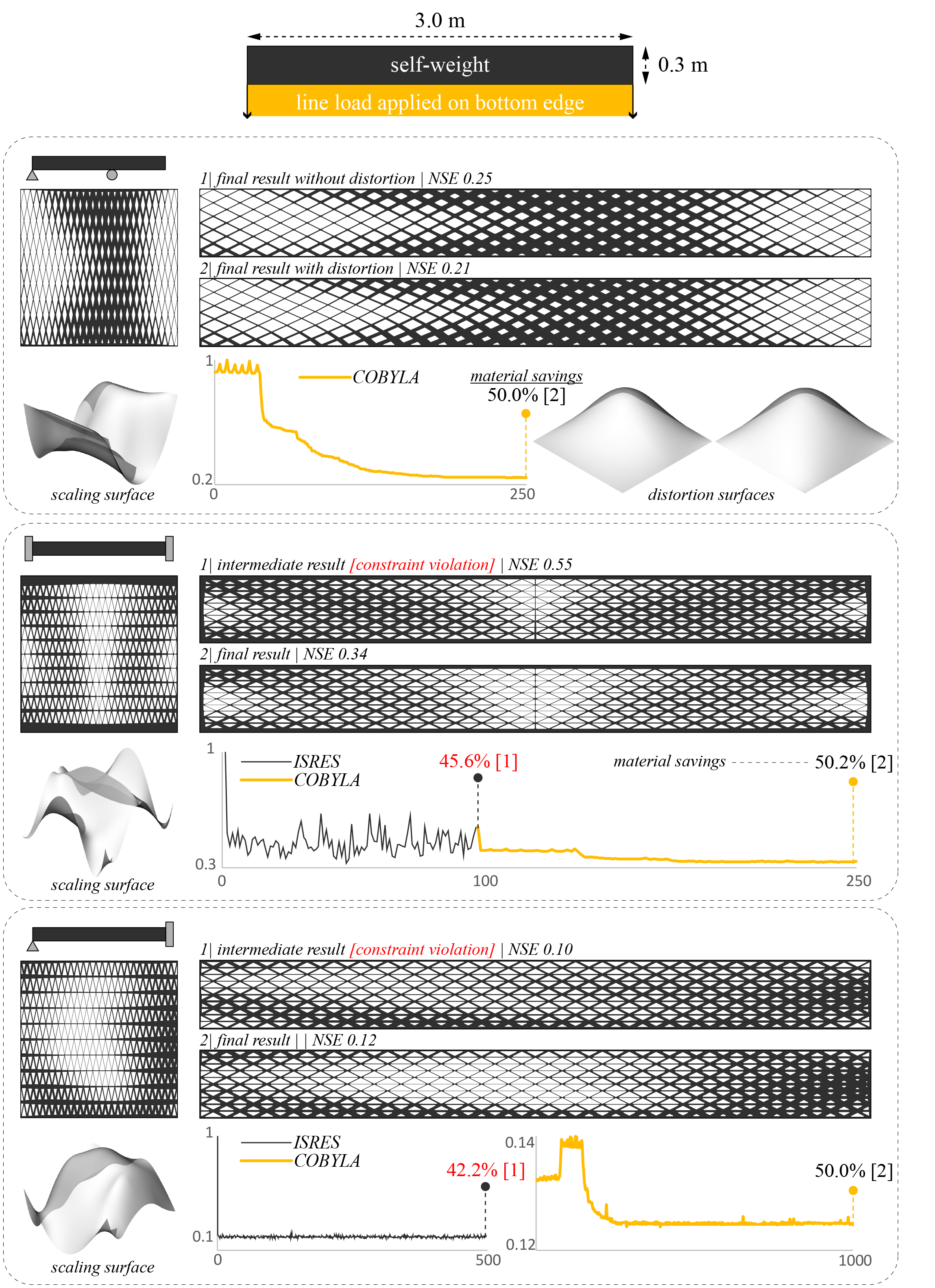
A steel prismatic beam is optimized for stiffness by introducing 500 perforations generated by the workflow above. Compliance, measured in terms of strain energy in a plane stress regime, is minimized, and the problem is constrained by a minimum material saving target of 50%. Optimization is performed using Radical with a sequential application of two optimization algorithms.
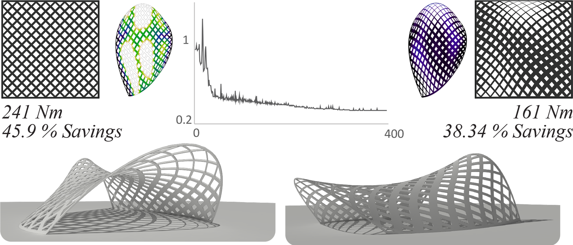
The power of the ideas presented here is best illustrated when applied on curved shells. Indeed, the methods do not require physical surface trimming, and all geometric operations applied on the pattern are two-dimensional. As a result, the optimization process is less computationally expensive and geometric operations remain tractable. A doubly curved shell is optimized for strain energy with a savings target of minimum 30%.
This work was published and presented at the Design Modelling Symposium 2017 in Paris and at the Engineering Mechanics Institute Conference 2018 in Boston.