Isogeometric analysis gives a way to link geometrical and structural design early on in the design process, and also provides streamlined modelling workflows between parameter and physical space. When extended to support trimmed geometries, it becomes a powerful method to analyze and design patterned structures.
With Caitlin Mueller
At the beginning of my PhD, I developed a new analysis method for trimmed surfaces—i.e. surfaces with apertures—based on isogeometric analysis (IGA). In short, IGA is an analysis method similar to finite element analysis (FEA) in most regards, but, instead of relying on a meshed representation of a geometry to analyze, it seeks to take advantage of the intrinsic computational representation of the geometry (curve, surface, solid) to solve the boundary value problem at hands (e.g. linear static analysis). In CAD, geometries are typically modeled using NURBS (and/or T-Splines in Autodesk products). They’re easy to use because they can be controlled intuitively via control points, and they support most surface modeling operations, such as lofts, extrusions, among others. IGA may seem esoteric, but, if you think of NURBS as a type of structured mesh with rational (similar to polynomial) basis functions where the control points have the role of nodes, it is nothing more than FEA with a fancy, structured mesh.
When I first came across IGA, I found it promising for integrating physical/structural simulations into CAD environments, which would allow users to get performance feedback/guidance while designing and ultimately leading to better outcomes.
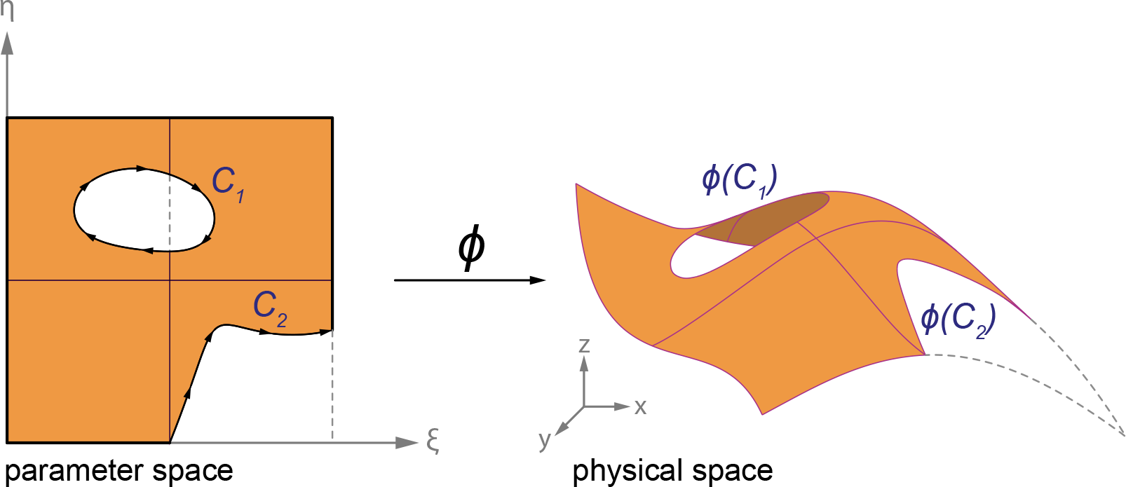
I was also interested into patterned structures, and I was particularly inspired by the work of the structural engineering office of Ney and Partners. IGA unfortunately does not lend itself naturally to the analysis of patterned surfaces because of the relatively rigid structure of NURBS surface. NURBS surfaces are bi-parametric, and it is easy to model a trimmed surface by defining curves in the parametric space of that surface. However, these curves are independent from the computational structure of the surface, and there is thus no straightforward way to take them into account for analysis. IGA requires integration over the parametric space, and one way to take trimming curves into account is simply to integrate over the solid domain and discard the void. Of course, integrating rational functions numerically over irregular domains is not trivial.
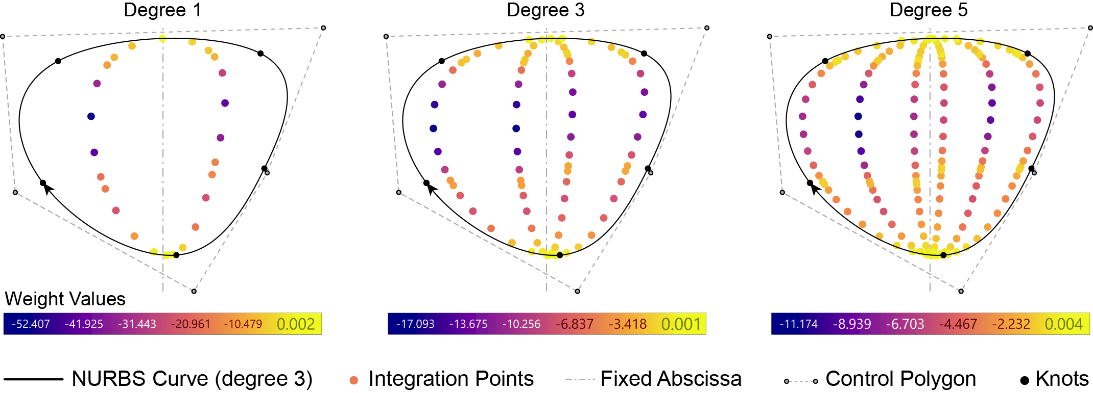
Previous research had focused on refining the NURBS surface to obtain regular integration cells in the parameter or reconstructing the NURBS surface into more connected surfaces altogether. I wanted to develop a method that would not require refinement. The technique I developed relies on a numerical formula for integration over domains enclosed by arbitrary NURBS curves based in Green’s theorem and on a recursive algorithm to identify and build integration regions for each cell/element in the parametric space.
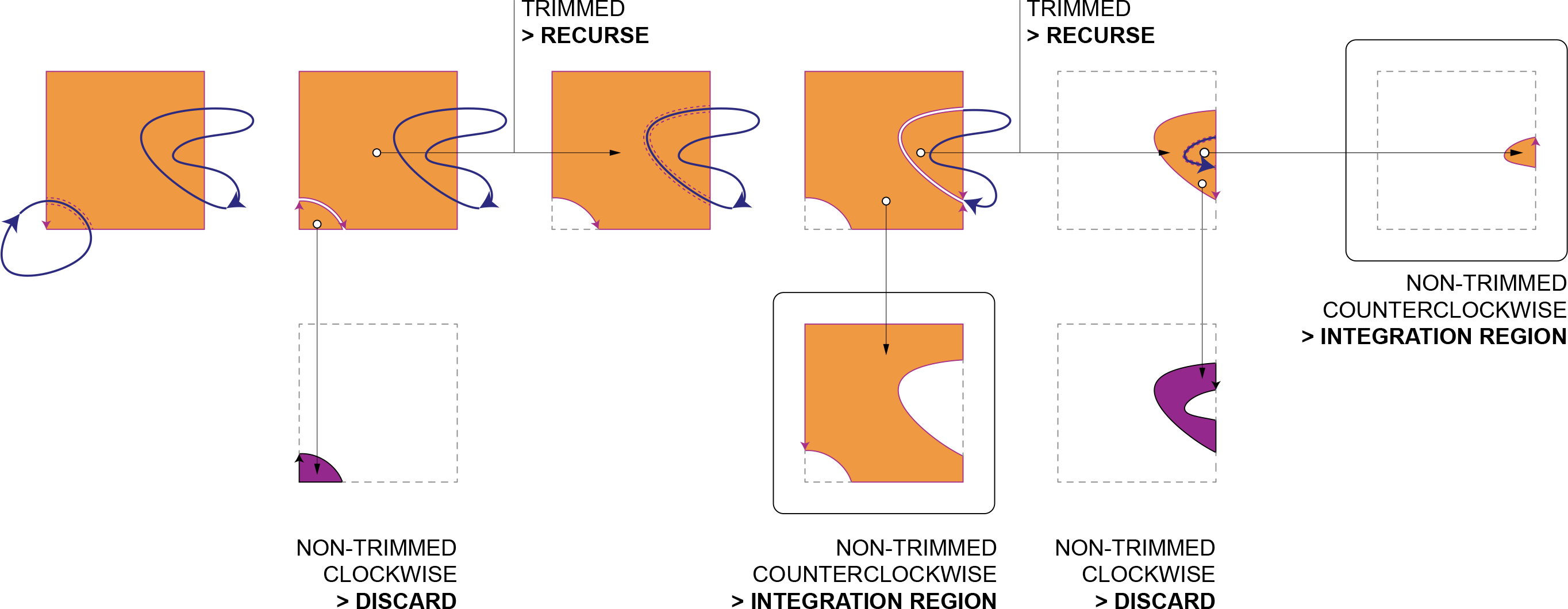
As mentioned above, I needed a way to build irregular integration regions for trimmed cells in the parametric space that would work for any trimming pattern. The solution is a recursive algorithm relying on intersections found between the trimming curves and the integration cells.
I implemented IGA for 2D plates (plane-stress formulation) and 3D shells (Kirchoff-Love formulation) in C# as a plug-in for the Rhino/Grasshopper CAD platform, and I also added the necessary features to support trimmed surfaces. As most of my research code, it used to be hosted on my enterprise MIT github account. I’ve just made it available on my personal account, but it needs to be refactored, as there are lots of redundant classes that could be dispensed with.
As with any new numerical method, it had to be validated against tried-and-tested techniques. In this case, I compared the results provided by trimmed surface analysis against solutions found by Abaqus, an industry-grade FEA software, for two different examples: a 2D plane stress problem and a 3D shell. The results show good convergence of the new method.
The plane stress problem is a simple cantilevering plate with four circular apertures described by degree-2 NURBS curves. The overall configuration, including geometry, boundary conditions, and material properties, is shown below (all numerical properties and results are unitless).
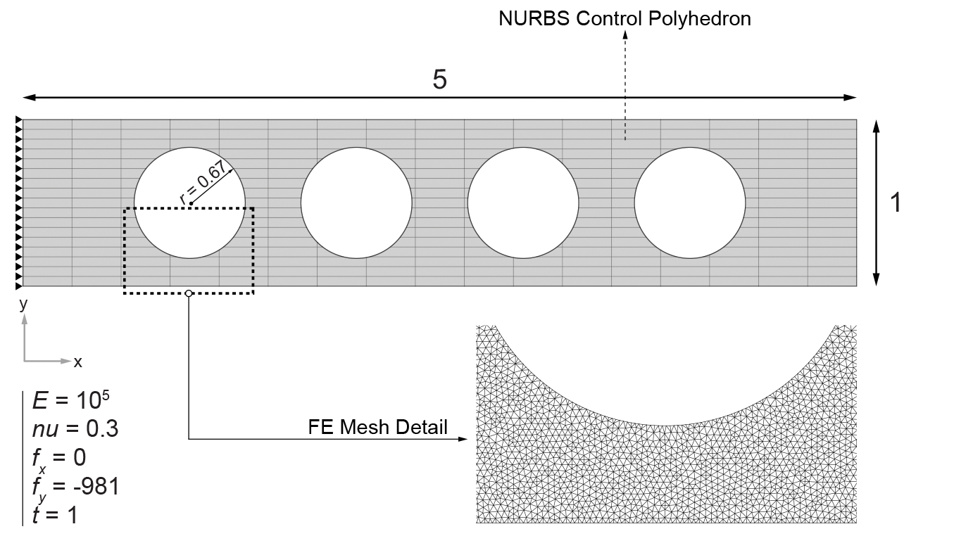
To analyze the accuracy of the IGA solution as a function of the resolution of NURBS, i.e. the number of control points, a very fine mesh is used—with a maximum length of 0.01, as shown above—as the baseline, and the convergence of this paper’s method is compared to the FEA solution. The structure is subject to the downward vertical body load, and the visualization below shows that the Von Mises stress solution for the coarse resolution—20-by-20 control points—approaches the overall stress distribution fairly well, while the predicted stress concentrations around the apertures are off by up to 20%. Comparatively, the finer solution—55-by-55 control points—converges to the FEA results well, which is also true in the direct vicinity of the aperture boundaries.
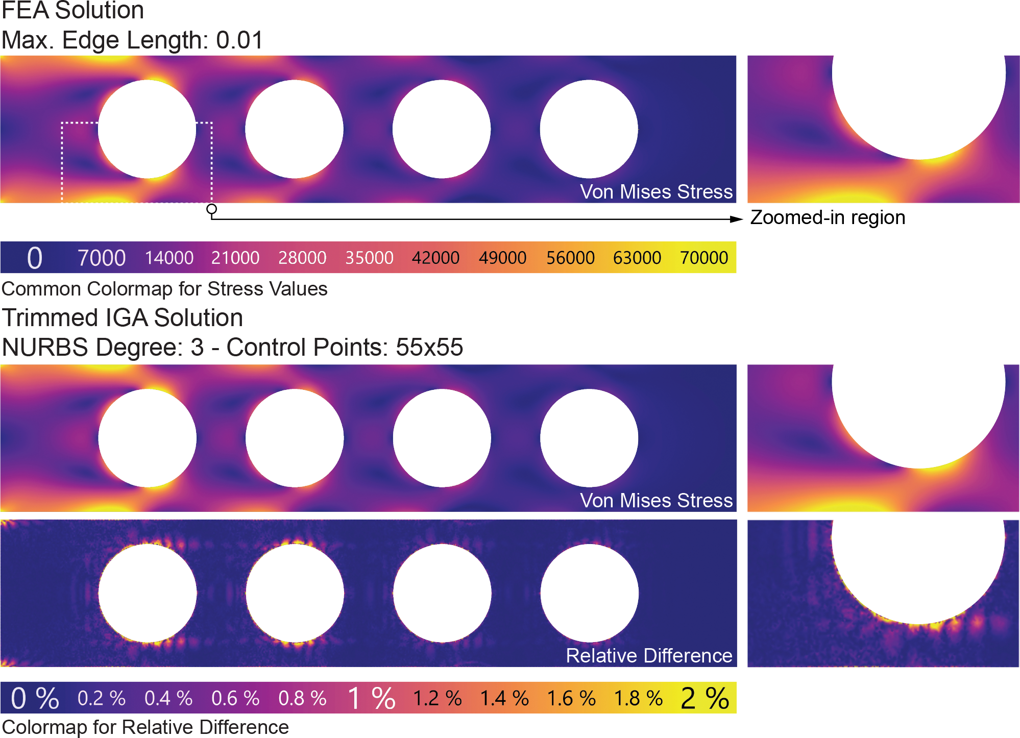
The results obtained on the problem described above validate that this paper’s method accurately models the response of a plane stress structure in a linear elastic regime as compared to the results provided by a very fine mesh analyzed using industry-grade FEA software.
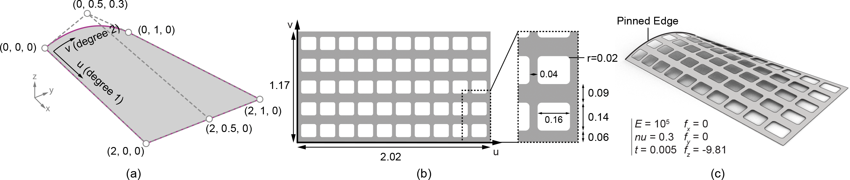
This example demonstrates the convergence of the method on a linear static shell analysis problem, for which the Kirchoff-Love formulation adapted to IGA by Kiendl et al. (2009) is used and extended with this paper’s algorithm and integration method for trimmed cells. The structure is a doubly-curved shallow shell and is supported along its single curved edge. The structure is punctuated by 50 rectangular apertures represented by degree-2 NURBS curves in the parametric space. It is subject to a downward vertical body force. Because of the symmetrical configuration of the structure, only a single half of it is analyzed.
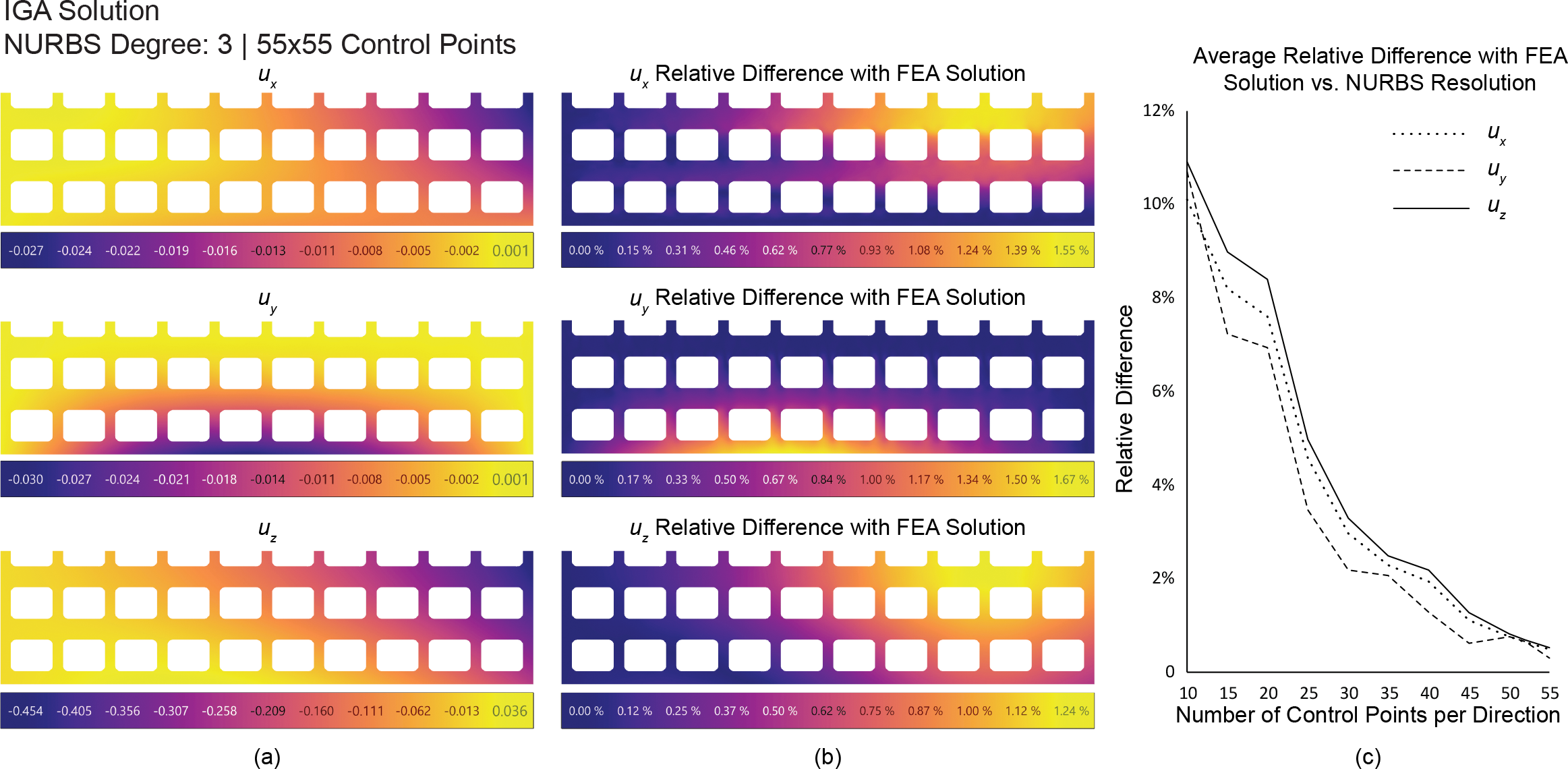
The structure is analyzed using both the method introduced and FEA using Abaqus, and the results are compared. In order to ensure a fair comparison between both methods, the FEA analysis is performed using a very fine mesh with triangular plate bending elements. The visualization below shows the displacement fields predicted by our method when applied on a fine NURBS surface (55 by 55 control points) and how they compare with the FEA solution. As for the plane stress problem, the solution approaches the FEA solution found on a very fine mesh, as illustrated by the evolution of the average relative difference as a function of the number of control points.
Because the method does not require refinement, it allows to analyze surfaces with complex trimming patterns with low-resolution NURBS. In addition, there is no need to trim the surface in the 3D which may sometimes be computationally expensive. This makes the method well-suited for early-stage pattern design optimization.
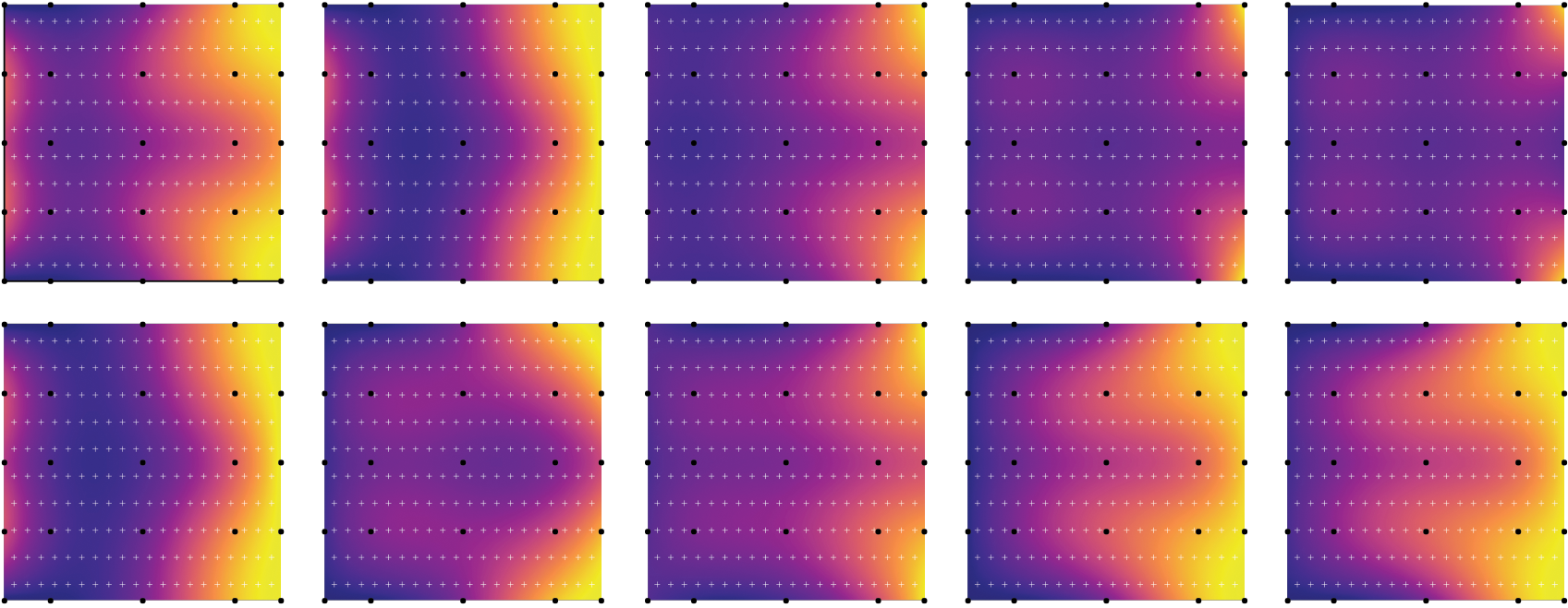
Optimization procedures do not necessary require high-fidelity analysis models because the analysis is still able to capture the global behavior of the structure, even if the absence of refinement leads to relatively poor analysis of the regions near trimming curves for low NURBS resolutions. While other IGA-based analysis methods require a minimum amount of refinement to provide results, the present method can do so with arbitrarily low model resolution. Since structural optimization is often concerned with minimizing global structural scalar functionals, such as weight or compliance, it justifies the use such low-resolution models. Further refinement can still be introduced in later stages of the optimization to refine the solution. To demonstrate the cogency of this approach, a constrained shape optimization problem is solved using this paper’s method with different resolution levels. It is shown that low-resolution models approach the solution found using the higher-resolution models.
The problem setup is similar to the convergence example above, and the shell is made with steel. The loading includes a gravity load applied over the whole structure and a downward vertical line load of 3 kN/m applied at the free curved edge. A rectangular trimming pattern is defined in the parametric space of the surface describing the structure. The goal of the optimization is to scale the trimming curves in each parametric direction such that the amount of material used is minimized while satisfying a constraint on the maximum displacement of the structure. As such, this is a shape optimization problem.
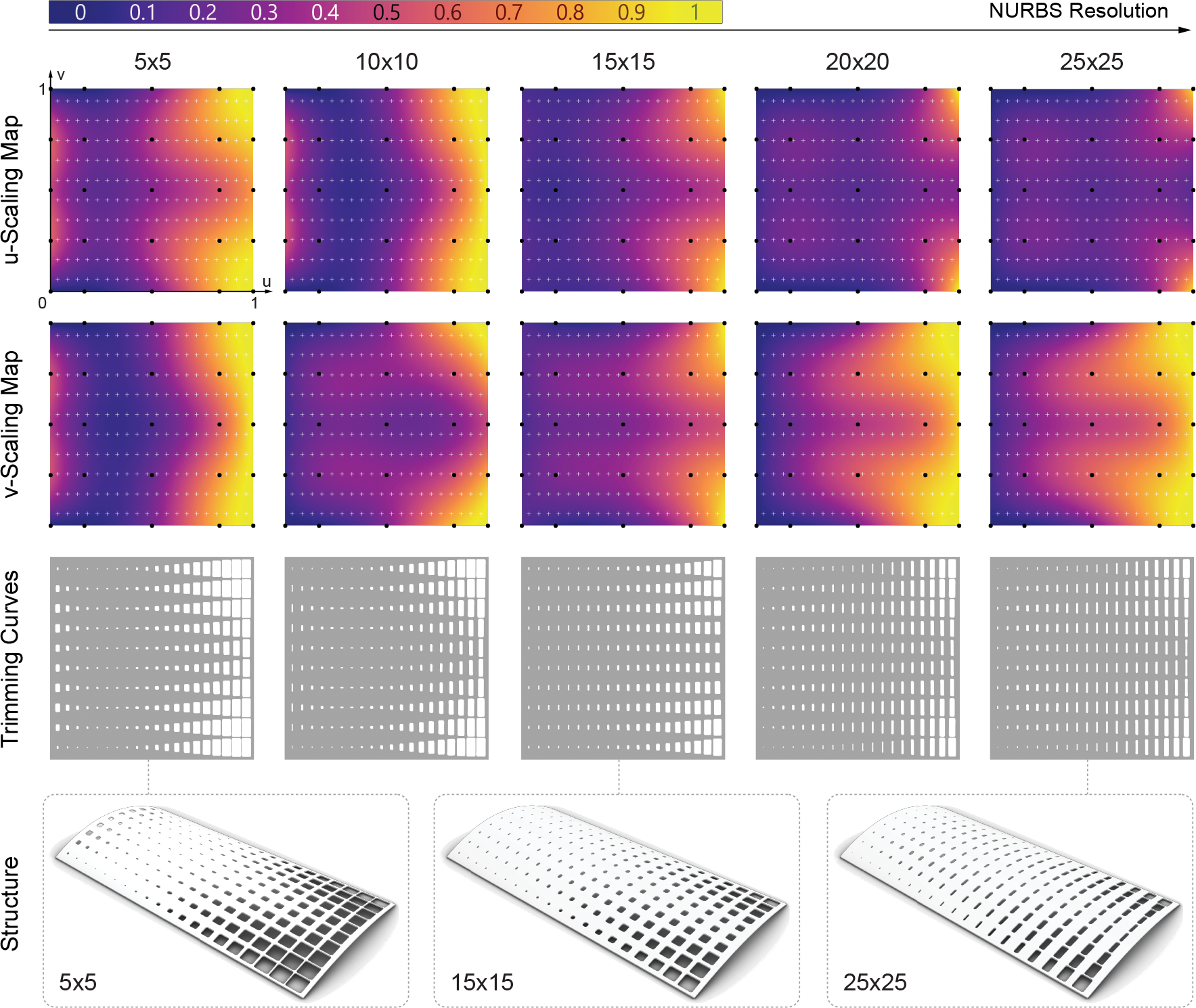
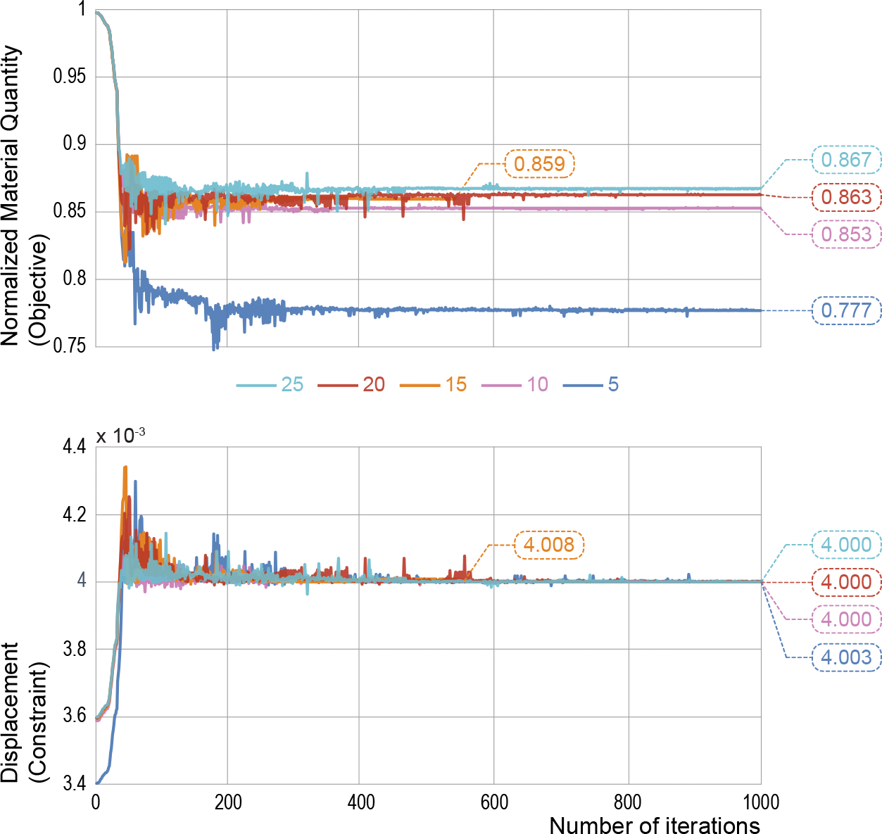
The results shown above show that, even for the coarsest resolution, intuitively sensible results are found, confirming the hypothesis that low-fidelity analysis is sufficient to steer the optimization process. Moreover, even if the optimal structures found using the different resolutions levels differ, there is a smooth convergence of the optimal height maps towards the high-resolution solution. This convergence is observed in the scaling maps and in the final objective values as reported below.
The power of IGA gives a way to link geometrical and structural design early on in the design process, and also provides streamlined modelling workflows between parameter and physical space. The method introduced expands on this potential specifically for surfaces featuring dense, complex patterns that can be optimized for structural performance, by proposing a method that offers a refinement-free alternative for analyzing and designing such surface structures.
This project has recently been submitted for publication to Computer Methods for Applied Mechanics and Engineering.